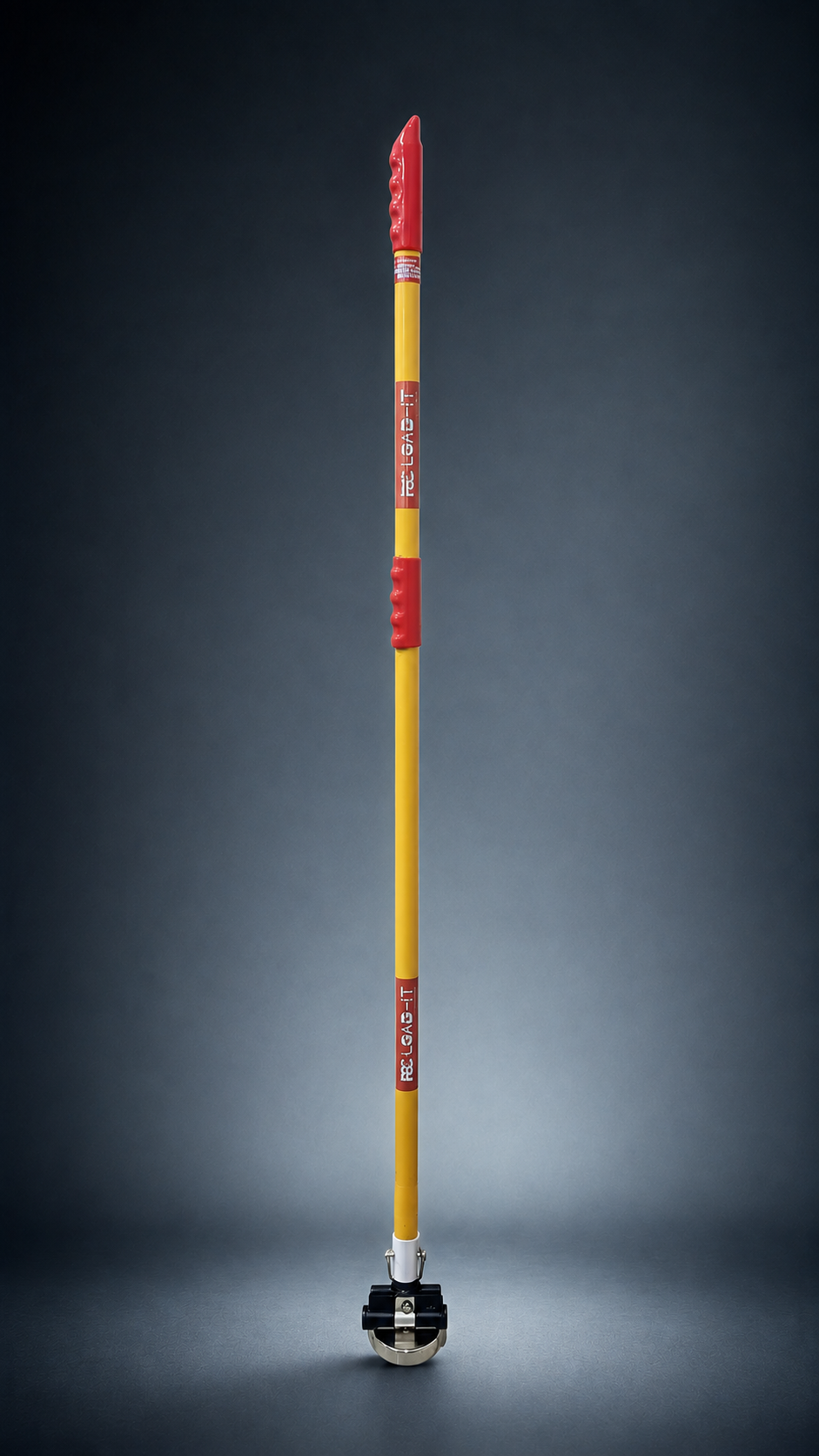
Axis 01
Centre over studs
The component must be positioned laterally over the mounting pattern.
Layer 3 · Application Article · PSC Hand Safety
Machinery installation creates some of the most concentrated hand exposure in industry: a heavy component, a precise mounting requirement, and a closing gap between the component and its seating surface.
The Stud Alignment Problem
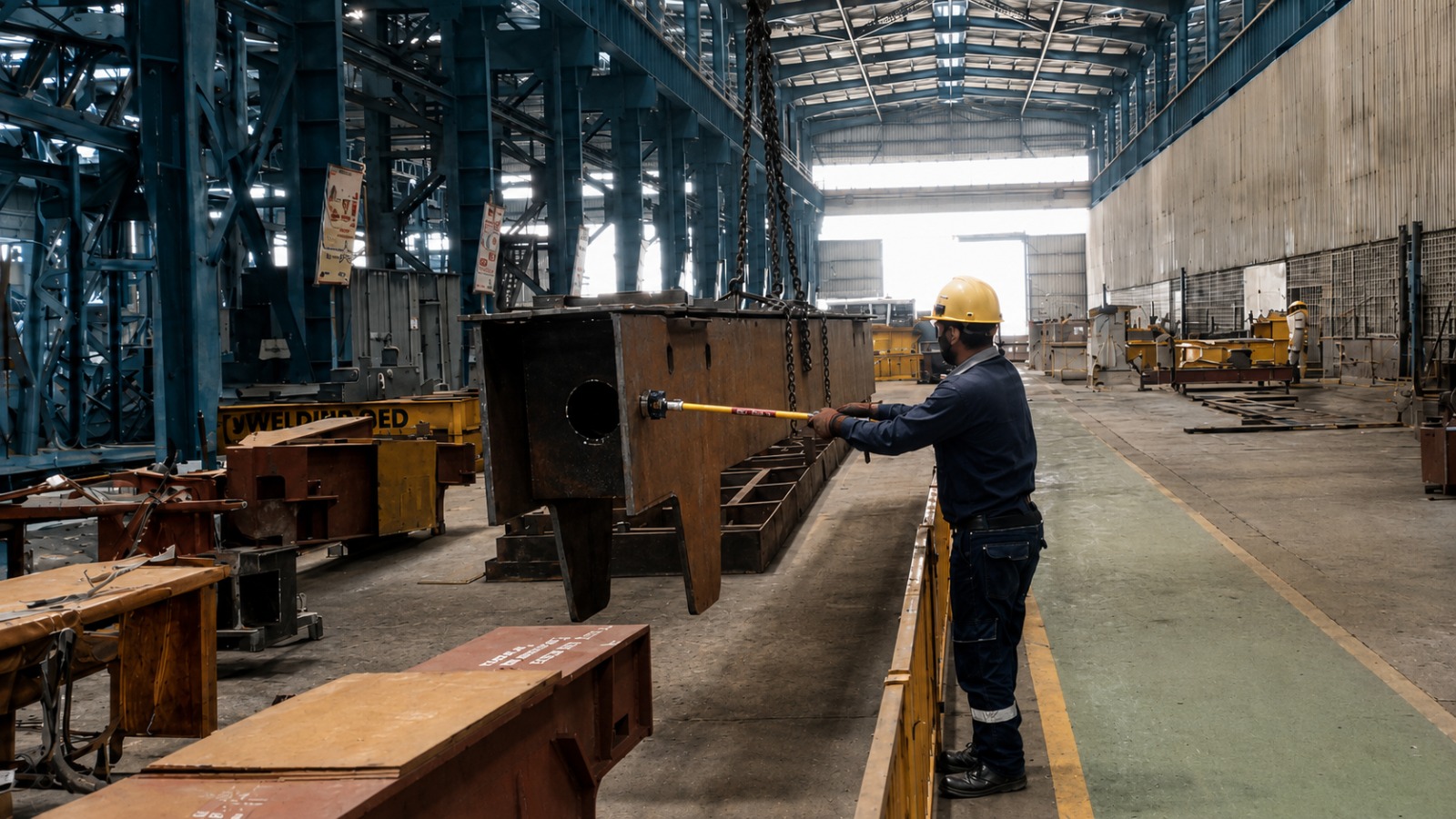
Installing a motor or gearbox onto mounting studs requires the component to be lowered precisely — often onto studs with close tolerances — while the operator guides the final approach.
The traditional method places fingers on the housing to feel the stud alignment and guide the last few millimetres of descent. That places the hand in the closing gap between the component and the mounting frame.
Alignment is required in multiple axes simultaneously: the component must be centred over the stud pattern, oriented correctly, and lowered squarely without tilting. Workers traditionally use their hands to feel when the studs begin to engage, guiding the component's final descent by tactile feedback.
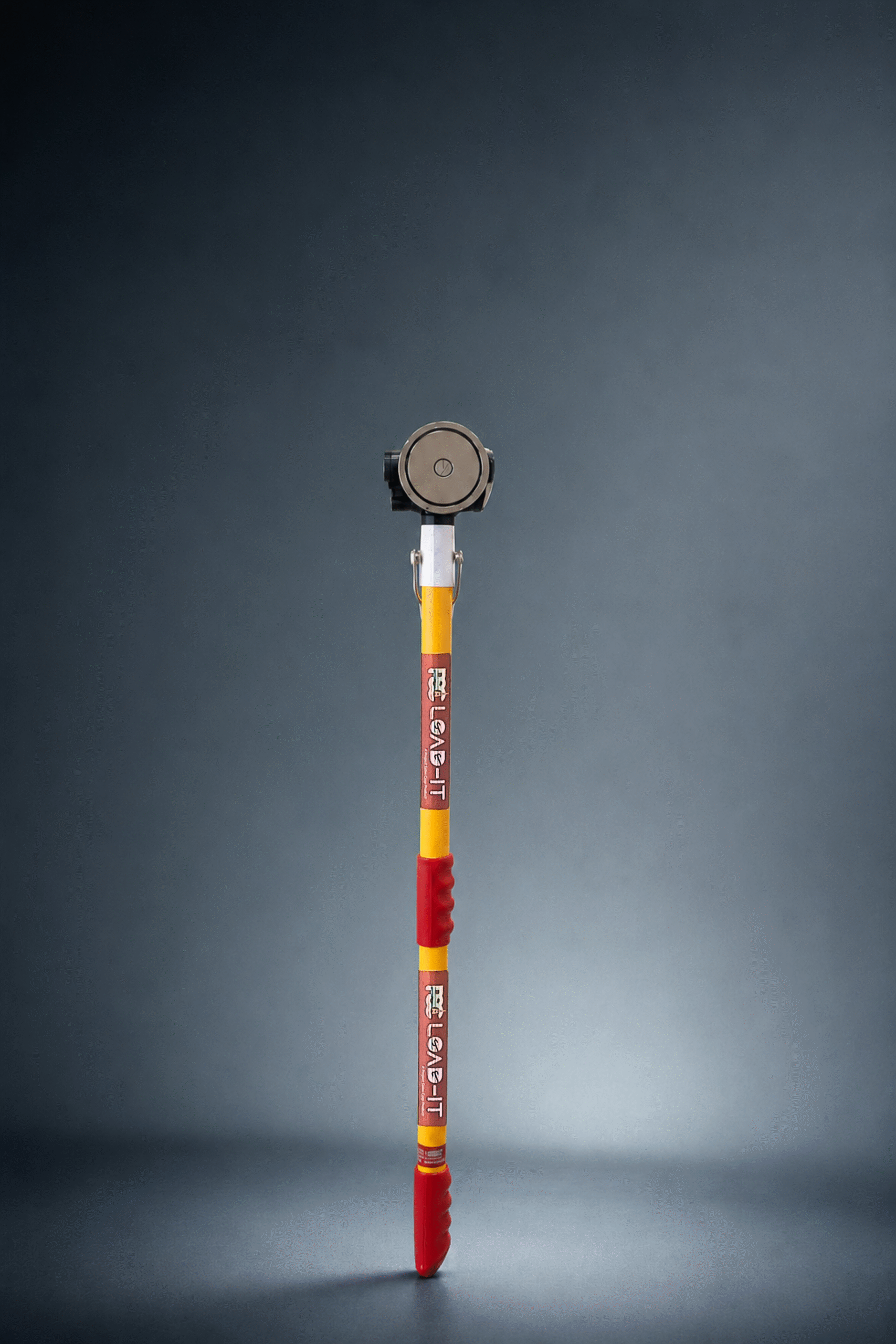
A magnetic push-pull tool applied to the housing face replicates the lateral and rotational correction this requires — without the hand entering the closing gap between housing and mounting frame.
The component must be positioned laterally over the mounting pattern.
Rotational correction may be required before the stud pattern begins to engage.
The component must descend without tilting as the mounting points engage.
Tool Selection for Machinery Installation
The approach direction onto mounting studs is typically single and predictable — the component descends from above onto a fixed mounting surface, with lateral correction required as the studs approach their holes.
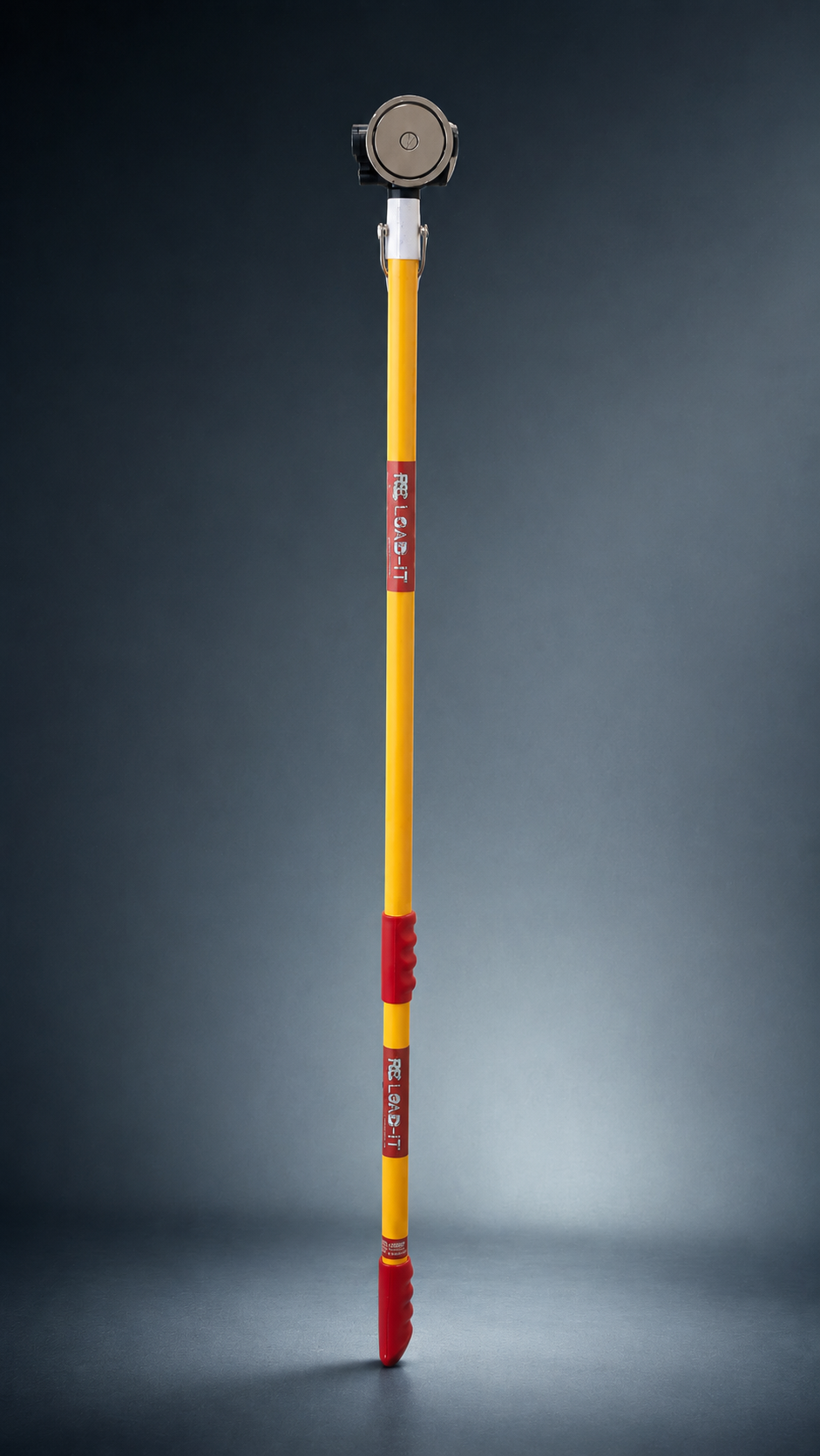
The 90° Flex Head on a 1–2 ft tool (MG002) is appropriate: maximum precision at close range, suited to the confined geometry of a machinery mounting task, and no excess reach to reduce control.
Matched to a single, predictable vertical approach onto a fixed mounting surface.
Close-range reach for precision in confined machinery-mounting geometry.
The tool provides the corrections needed to bring the housing into stud alignment.
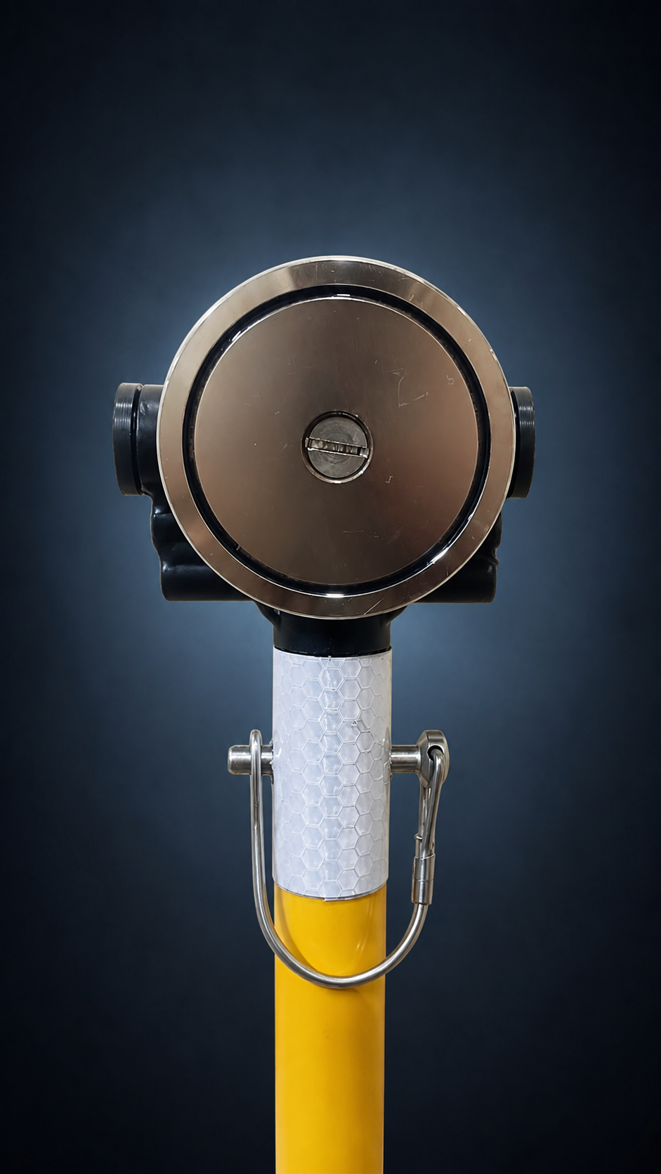
Painted and Coated Housings
Motor and gearbox housings are routinely coated for corrosion protection.
Paint layers reduce magnetic attachment quality. A light test pull to verify engagement before the final lowering sequence is particularly important for this application — the operator cannot afford a loss of magnetic contact during the critical stud-alignment phase.
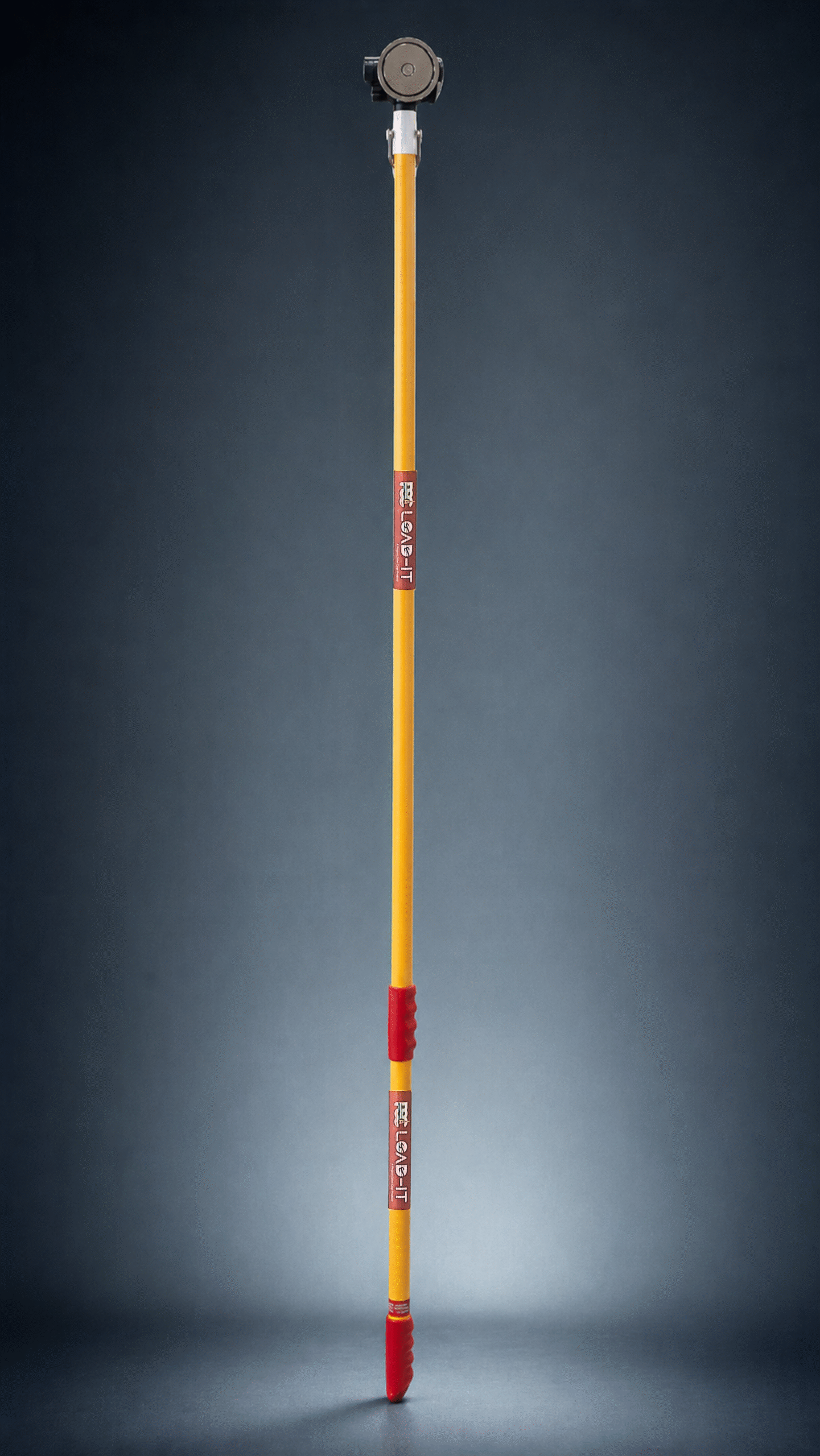
Application Note
The magnetic tool provides lateral and rotational guidance. The crane remains responsible for vertical descent rate.
Do not use the tool to resist or slow the vertical descent — it is a guidance interface, not a braking device.
The crane controls the vertical lowering sequence. The magnetic tool provides directional guidance only.
Related Engineering Resources
Review the MagHead system, selection logic, magnetic-force engineering and the wider hands-free ferrous-load guidance framework.
Premium Engineering Consultation
PSC's Application Mapping Review examines the actual task — the load, the surface, the access conditions, and the operator's movement — and recommends the correct matched configuration.